Skip to content
← All lessons

LESSON 03

Control surfaces

Airplane control surfaces change aerodynamic forces to control roll, pitch, and yaw. Ailerons primarily control roll, the elevator or stabilator controls pitch, and the rudder controls yaw.

Checking your account…

Your learning goals

  • Match roll, pitch, and yaw to their axes and primary controls.
  • Explain adverse yaw and why coordination matters.
  • Distinguish the jobs of flaps, trim, and other secondary controls.

01 / FROM FORCE TO ROTATION

Three axes. Three primary motions.

Moving a control surface changes airflow and pressure around the wing or tail. The resulting force acts through a lever arm to create a moment—a tendency to rotate.

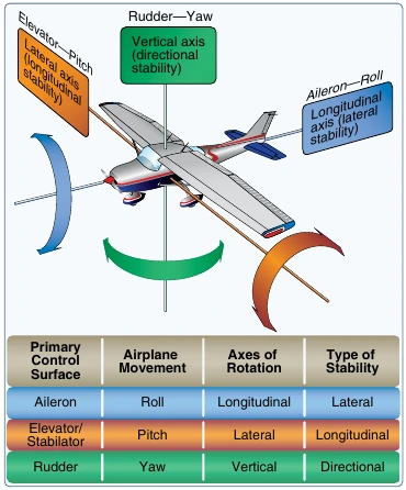
We describe rotation using three aircraft axes through the center of gravity (CG). The airplane can translate through space while rotating about these axes.

Airplane roll, pitch, and yaw axes with their primary controls and related stability types
FAA PHAK · Figure 6-4. Select image to enlarge.
Roll → longitudinal axis
Nose to tail. Primarily controlled by ailerons.
Pitch → lateral axis
Wingtip to wingtip. Primarily controlled by the elevator or stabilator.
Yaw → vertical axis
Through the CG, perpendicular to the other two aircraft axes. Primarily controlled by the rudder.

The vertical axis moves with the airplane; when banked, it need not point straight toward the ground.

FAA · PHAK Chapter 6, pp. 6-3

03 / PUT IT TOGETHER

Follow the force.

For any surface, ask: What moved? How did the aerodynamic force change? Where does that force act relative to the CG?

Explore deeper · Check yourself: right roll, left yaw

The right aileron rises and the left lowers. The lift difference rolls the aircraft right, while the drag difference can initially yaw it left. That opposite yaw is adverse yaw.

Explore deeper · Check yourself: elevator or stabilator?

If only the hinged trailing edge moves, it is an elevator. If the whole horizontal tail pivots, it is a stabilator. Both control pitch about the lateral axis.

Explore deeper · Check yourself: does a flap control pitch?

A flap’s main job is to change the wing’s lift and drag characteristics. Extension can cause a pitching moment, but that secondary effect does not make it the primary pitch control.

Control effectiveness depends on local airflow, deflection, and aircraft design. A jammed surface and a disconnected linkage are different failures; trim may not remain effective in both. Aircraft-specific limitations and procedures belong in the approved POH/AFM.

← Revisit angle of attack & stalls

02 / EXPLORE THE CONTROLS

Choose a surface.

Compare its location, action, axis, and common designs.

ROLL · LONGITUDINAL AXIS

Ailerons

Ailerons are hinged surfaces near the outboard trailing edges of the wings. They normally move in opposite directions. A right control input raises the right aileron and lowers the left.

The lowered left aileron increases local camber and lift; the raised right aileron reduces them. This difference creates a rolling moment: the left wing rises and the right wing lowers. Roll is rotation about the nose-to-tail, or longitudinal, axis.

Right roll input → right aileron up, left aileron down.
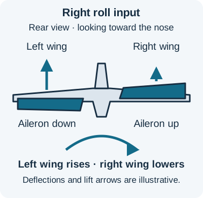
Rear view, looking toward the nose: left aileron down increases local lift; right aileron up reduces local lift. The left wing rises and the right wing lowers.
Right roll input, viewed from behind. Original teaching diagram based on FAA PHAK Chapter 6. Select image to enlarge.
Explore deeper · Camber, AOA, and adverse yaw

Camber is the curvature of an airfoil. Deflecting an aileron changes the section’s shape and pressure distribution. It can change lift coefficient at the same geometric AOA; it does not require the entire wing to rotate to a new AOA.

During roll initiation, the wing with the down aileron generally produces more lift and induced drag. Unequal drag tends to yaw the nose opposite the commanded roll. A right roll can initially produce left yaw. This is adverse yaw. Local airflow changes during rolling also contribute.

Appropriate rudder input counters the yaw. The amount depends on the aircraft and conditions; matching aileron and rudder does not mean using equal control travel.
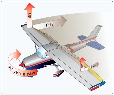
Unequal lift and drag on the wings create adverse yaw opposite the roll
FAA PHAK · Figure 6-5. Select image to enlarge.

FAA · PHAK Chapter 6, pp. 6-3–4

Aileron designs

Conventional
Opposite deflections change the lift on each wing to create roll.
Differential
The up-going aileron travels farther than the down-going aileron. The resulting drag balance reduces adverse yaw.
Frise-type
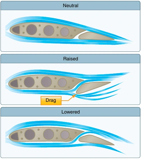
An offset hinge lets the leading edge of the raised aileron project below the wing, adding drag on that side. A Frise aileron can also use differential travel.
Flaperons
A mixer combines differential movement for roll with common downward movement for the flap function.
Coupled aileron and rudder
An interconnection adds rudder with aileron input. This is a control-system arrangement, rather than a different surface shape.

These designs can reduce adverse yaw; they do not guarantee coordination in every condition.
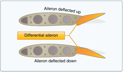
Two wing sections showing greater upward than downward aileron travel
Differential ailerons: unequal travel helps reduce adverse yaw. FAA PHAK · Figure 6-6. Select image to enlarge.
Neutral, raised, and lowered Frise ailerons; the raised aileron projects into the airflow below the wing
FAA PHAK · Figure 6-7. Select image to enlarge.

FAA · PHAK Chapter 6, pp. 6-3–5

PITCH · LATERAL AXIS

Elevator & stabilator

The elevator is a hinged surface on a fixed horizontal stabilizer. A stabilator is an all-moving horizontal tail. Both control pitch about the wingtip-to-wingtip, or lateral, axis.

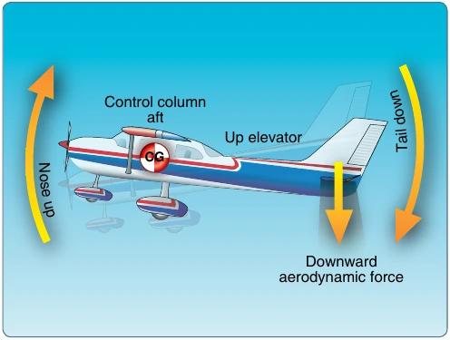
On a conventional aft-tail airplane, pulling back raises the elevator’s trailing edge. The change in pressure produces a more downward tail force, creating a nose-up pitching moment about the CG. Pushing forward reverses that change.

A force at the tail acts through a lever arm to change pitch.

Elevator up changes tail force downward and pitches the nose up about the center of gravity
FAA PHAK · Figure 6-10. Select image to enlarge.

Two ways to change the tail force

Elevator
The stabilizer stays fixed while its hinged trailing edge moves, changing the combined section’s camber.
Stabilator
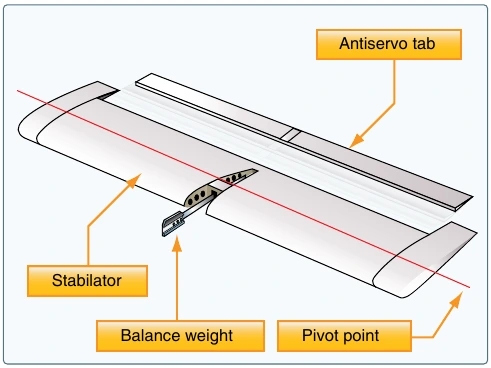
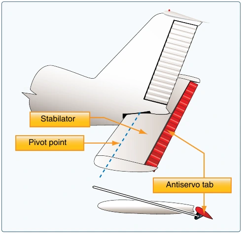
The whole horizontal surface pivots, changing its incidence to the local airflow. Many use an antiservo tab to increase control force and reduce sensitivity.
All-moving stabilator with pivot point, balance weight, and antiservo tab labeled
FAA PHAK · Figure 6-13. Select image to enlarge.
Explore deeper · Tail arrangements and control authority

A T-tail describes where the horizontal tail is mounted, not whether it uses an elevator or stabilator. At high AOA, separated wing airflow can blanket the horizontal tail on some designs and reduce pitch authority.

A canard is a forward surface. When used for pitch control, its force acts ahead of the CG, so the aft-tail explanation cannot simply be copied to it. A V-tail uses mixed ruddervators for pitch and yaw.

The pitching moment depends on the tail-force change and its distance from the CG. Actual tail loading varies with design, loading, and flight condition; an aft tail does not always produce a downward net force.

FAA · PHAK Chapter 6, pp. 6-5–8

FAA · PHAK Chapter 6, pp. 6-5–8

YAW · VERTICAL AXIS

Rudder

The rudder is hinged to the trailing edge of the vertical stabilizer. It controls yaw: the nose moves left or right about the vertical axis through the CG.

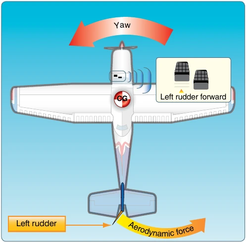
Pressing the left rudder pedal deflects the rudder left. The fin and rudder produce a side force toward the right at the tail, yawing the nose left. Right pedal gives the opposite response.

Rudder helps counter adverse yaw and other yawing tendencies. It also allows deliberate sideslip when appropriate. In a normal coordinated turn, the banked wing’s lift supplies the main turning force.

Left pedal → rudder left → tail force right → nose yaws left.

Top view: left pedal and left rudder create a rightward tail force and leftward nose yaw
FAA PHAK · Figure 6-15. Select image to enlarge.

Rudder arrangements

A conventional tail uses a separate rudder on a vertical fin. Some aircraft have multiple fins and rudders. A V-tail uses ruddervators: mixed surfaces that move together for pitch and differentially for yaw. The pilot still has separate pitch and rudder controls.

Explore deeper · Why rudder effectiveness changes

For the same deflection, aerodynamic force generally increases with the local airflow speed and density. Propeller slipstream can increase airflow over the rudder. A pedal input therefore does not correspond to one fixed amount of yaw in every condition.

Yaw and roll can also interact through the aircraft’s aerodynamic design. We’ll connect those effects to directional and lateral stability in the stability lesson.

FAA · PHAK Chapter 6, pp. 6-8

FAA · PHAK Chapter 6, pp. 6-8

HIGH LIFT · NO DEDICATED ROTATION AXIS

Flaps

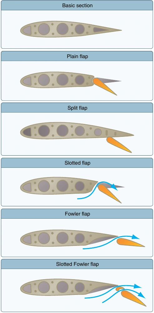
Flaps are usually fitted to the inboard trailing edge of each wing and extend together. They increase camber, and some designs also increase wing area. Their purpose is to change lift and drag characteristics, rather than command pitch, roll, or yaw directly.

Extension generally increases maximum lift coefficient, allowing a lower stall speed for the same weight and load factor. It also increases drag. Smaller settings often give a favorable lift increase; larger settings usually add proportionally more drag.

There is no universal “first two notches for lift, last notch for drag” rule. The design and setting matter.

Cross sections compare plain, split, slotted, Fowler, and slotted Fowler flaps
FAA PHAK · Figure 6-17. Select image to enlarge.

Compare the flap types

Plain
The trailing edge hinges downward as a unit, increasing camber.
Split
Only the lower portion deflects. The upper contour stays in place, leaving a large wake and substantial drag.
Slotted
A gap feeds energetic airflow to the flap’s upper surface, helping delay separation and increase maximum lift coefficient.
Fowler
The flap moves aft and then down, increasing wing area as well as camber. Fowler arrangements commonly incorporate slots.
Multiple-slot Fowler
Several elements and slots support larger camber changes while helping the airflow remain attached.
Explore deeper · Flaps, pitching moment, and asymmetric extension

Flaps alter the wing’s pressure distribution and downwash at the tail. The resulting aircraft pitch response can be nose-up or nose-down, depending on the design. Configuration changes can require retrimming.

A split flap is a normal flap design. Asymmetric flap extension is a different condition: the two wings have unequal flap positions. Unequal lift and drag can produce roll and yaw. The response to a failure depends on the aircraft and its approved procedure.

Use the aircraft’s POH/AFM for flap limits, approved settings, and abnormal procedures. Flaps do not prevent a stall if critical AOA is exceeded.

FAA · PHAK Chapter 6, pp. 6-8–9

FAA · PHAK Chapter 6, pp. 6-8–9

CONTROL FORCE · AXIS DEPENDS ON THE CONTROL

Trim & control tabs

Trim relieves the steady force needed to hold a chosen flight condition. It may act on pitch, roll, or yaw, depending on which control is trimmed. Establish the desired condition first, then trim away the sustained control pressure.

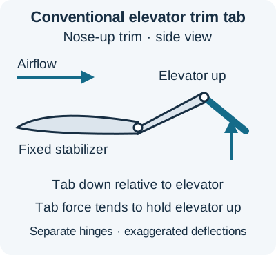
A conventional elevator trim tab is a small hinged surface at the elevator’s trailing edge. For nose-up trim, the tab typically moves down relative to the elevator. Aerodynamic force on the tab tends to hold the elevator up.

A trim tab’s setting is controlled separately. Pulling the yoke does not automatically command nose-up trim.

Conventional elevator trim tab: for nose-up trim, the tab deflects down relative to the elevator; aerodynamic force on the tab tends to hold the elevator up.
Conventional elevator trim tab. Original teaching diagram based on FAA PHAK Figure 6-20. Select image to enlarge.

Similar-looking tabs, different jobs

Trim tab
Adjusted to create a hinge moment that relieves sustained control force.
Balance tab
Linked to move opposite the primary surface, helping the pilot move it.
Servo tab
The pilot moves the tab; aerodynamic force on the tab moves the main control surface.
Antiservo tab
Moves farther in the same direction as the stabilator’s trailing edge, resisting movement and increasing control feel. It may also provide trim.
Ground-adjustable tab
Set on the ground to correct a steady tendency in a chosen flight condition.
Adjustable stabilizer
Changes the horizontal stabilizer’s incidence to trim pitch, rather than relying on an elevator trim tab.
An all-moving stabilator with an antiservo tab linked to move farther in the same direction as the stabilator’s trailing edge.
Stabilator antiservo tab: moves in the same direction to increase control feel. This is a different arrangement from the conventional elevator trim tab above. FAA PHAK · Figure 6-21. Select image to enlarge.
Explore deeper · Trim changes force balance

A tab works because its aerodynamic force acts at a distance from the main control’s hinge. A relatively small tab can therefore change the hinge moment the pilot feels.

An antiservo tab makes an all-moving tail less sensitive by increasing the force needed for additional deflection. This is a control-feel function, not a guarantee against overstressing the aircraft.

Trim is not an altitude hold system. Changes in airspeed, power, or configuration can change the force balance and require new trim.

FAA · PHAK Chapter 6, pp. 6-10–12

FAA · PHAK Chapter 6, pp. 6-10–12

LIFT AND DRAG · SPOILERS CAN ALSO CONTROL ROLL

Slats & spoilers

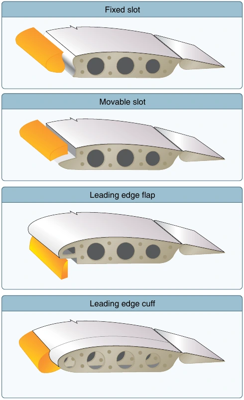
Leading-edge devices help the wing operate at higher lift coefficients. A fixed slot is a passage; a movable slat opens a passage when extended. Airflow through the gap helps delay separation over the upper surface.

Spoilers are panels that rise from the wing’s upper surface. They disrupt airflow, reducing lift and increasing drag. Symmetric deployment changes lift and drag; differential deployment can help command roll about the longitudinal axis.

Slats help delay separation. Spoilers deliberately disrupt the flow.

Fixed slot, movable leading-edge device, leading-edge flap, and fixed cuff shown in cross section
FAA PHAK · Figure 6-18. Select image to enlarge.

Leading-edge designs

Fixed slot
An always-open passage directs airflow onto the wing’s upper surface.
Movable slat
A leading-edge segment moves forward to open a slot. Actuation may be automatic or pilot commanded.
Leading-edge flap
A movable leading-edge section increases camber.
Leading-edge cuff
A fixed shape modification helps improve high-AOA airflow behavior; it is not a movable control.

Spoiler functions

Flight spoilers can add drag and reduce lift during descent. Roll spoilers reduce lift on the wing that is to lower. Ground spoilers reduce lift after touchdown, transferring more weight to the wheels for braking. Which panels do which job depends on the aircraft.

Separated airflow Raised spoiler → less lift, more drag

Simplified functional cross-section, based on FAA PHAK §Spoilers.

FAA · PHAK Chapter 6, pp. 6-9–10

FAA · PHAK Chapter 6, pp. 6-9–10

CHECK YOUR UNDERSTANDING

Explain it in your own words.

Think through each question before revealing the answer.

Which axis does the elevator primarily control?

Pitch about the lateral, wingtip-to-wingtip axis.

Why is rudder useful when using ailerons?

Rudder helps coordinate yaw, including countering adverse yaw during roll inputs.

What does trim do?

Trim reduces the sustained control force needed for the selected flight condition. It does not replace monitoring and controlling the airplane.

PRACTICE

Flashcards and knowledge check

Review six flashcards, then answer five questions.

Enable JavaScript for flashcards and the knowledge check. The lesson and scenario remain available without it.

Sources & lesson notes

Lesson sources

Based on your Control Surfaces lesson plan, with terminology and aerodynamic explanations checked against the FAA.

  1. FAA — Pilot’s Handbook of Aeronautical Knowledge, Chapter 6: Flight Controls

    Primary controls and axes: pp. 6-3–6-8. Flaps, leading-edge devices, and spoilers: pp. 6-8–6-10. Trim and tabs: pp. 6-10–6-12.

  2. FAA — PHAK publication page

    Official handbook and current supporting material.

Diagrams are cropped excerpts of FAA Figures 6-4, 6-5, 6-6, 6-7, 6-10, 6-13, 6-15, 6-17, 6-18, and 6-21. The spoiler cross-section is an original explanatory schematic. Diagrams show concepts, not aircraft-specific rigging or control travel.

Next lesson: Aerodynamics of turns →